Ever returned to your vehicle after a weekend adventure only to find your starter battery completely dead? You’re not alone—improperly installed dual-battery systems cause thousands of preventable breakdowns each year. Installing a NOCO battery isolator correctly solves this problem by automatically managing power between your starter and accessory batteries. This guide provides the exact installation procedures for both universal applications and GM-specific vehicles, ensuring your auxiliary power system works flawlessly when you need it most.
Whether you’re outfitting an overland rig, marine vessel, or daily driver with auxiliary power, the right NOCO battery isolator installation prevents cross-draining while maximizing charging efficiency. Following these precise steps will help you avoid common pitfalls that lead to system failures. You’ll learn which NOCO kit matches your vehicle, how to make professional-grade connections, and what to test before hitting the road.
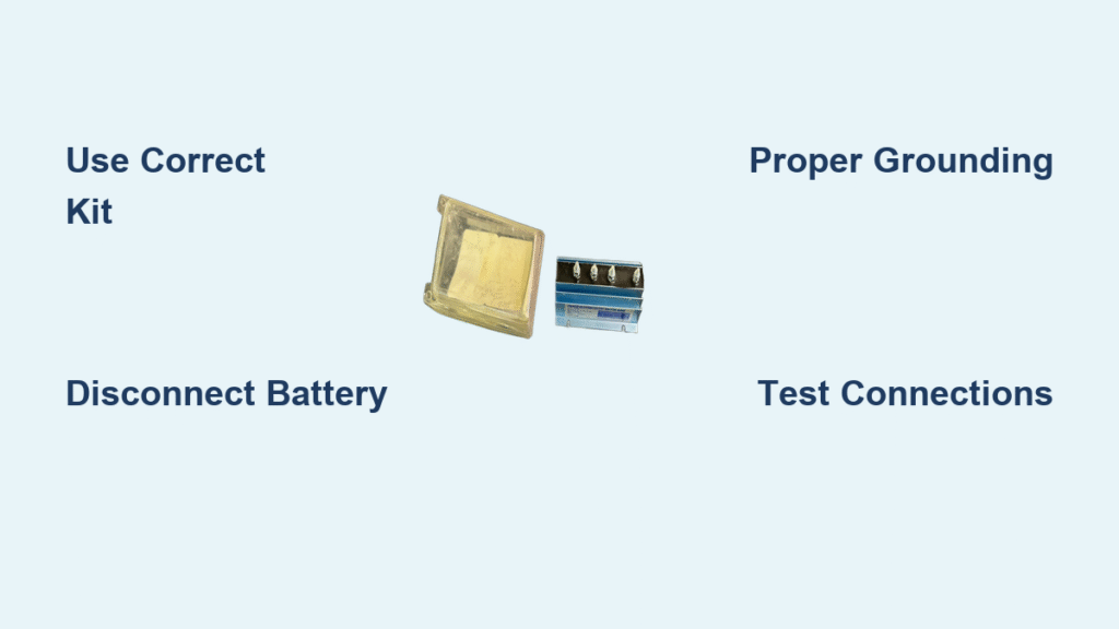
Select Your Correct NOCO Isolator Kit: IGK1550 vs IGK1440

Choosing the right NOCO installation kit determines whether your isolator functions properly or creates electrical problems. The IGK1550 universal kit contains complete wiring harnesses, cables, and connectors designed for any vehicle regardless of make or model. This comprehensive package eliminates the guesswork of sourcing individual components and includes everything needed for a professional-grade installation in under an hour.
GM-Specific Kit Requirements for CS-130D Alternators
If you drive a GM vehicle with a CS-130D alternator (common in trucks and SUVs from the late 1990s-2010s), you must use the IGK1440 kit instead of the universal option. This specialized kit includes a CS-130D plug-in connector that interfaces directly with Delcotron charging systems. Attempting to use the universal IGK1550 kit on these GM vehicles often results in improper alternator communication and potential charging system damage.
The IGK1440 kit contains seven heat-shrinkable connectors, a 20-amp circuit breaker, and the critical CS-130D connector that plugs directly into your vehicle’s alternator harness. This configuration ensures proper voltage sensing and prevents the isolator from connecting batteries at incorrect voltage thresholds—a common failure point in mismatched installations.
Critical Safety Steps Before Starting Your NOCO Isolator Installation
Battery Disconnection Protocol
Always disconnect your primary battery’s negative terminal before beginning work—this simple step prevents catastrophic short circuits that could damage your vehicle’s electrical system or cause injury. Use a 10mm socket to remove the negative cable and secure it away from the battery terminal. Wear safety glasses and insulated gloves throughout the installation process to protect against accidental sparks.
Workspace Safety Requirements
Park your vehicle on level ground with the parking brake engaged and wheels chocked. Ensure you have adequate lighting to see connection points clearly—working in dim conditions increases the risk of crossed wires. Keep a Class ABC fire extinguisher within arm’s reach, especially when working near battery compartments where hydrogen gas accumulation could occur.
Essential Tools Needed for Proper NOCO Battery Isolator Installation

Must-Have Installation Tools
You’ll need these basic tools regardless of which NOCO kit you select:
– Wire strippers/crimpers (not regular pliers—proper crimping is critical)
– Heat gun (a lighter works in a pinch for heat-shrink tubing)
– Socket set (10mm, 12mm, and 13mm cover most applications)
– Digital multimeter (for verifying connections and testing)
– Phillips and flathead screwdrivers (for accessing tight spaces)
Additional Supplies for Professional Results
Beyond the NOCO kit components, gather these often-overlooked items:
– Dielectric grease (prevents corrosion on all connections)
– Zip ties (for secure wire management—avoid tape which degrades)
– Split loom tubing (protects wires from chafing in high-movement areas)
– Star washers (ensures solid ground connections through paint)
Optimal Mounting Locations for Your NOCO Battery Isolator
Where to Position Your Isolator Unit
Mount the NOCO battery isolator in a dry location away from direct engine heat sources and moving parts. Ideal spots include the inner fender wall, firewall, or under rear seats in vehicles with relocated batteries. The mounting surface must be metal to serve as a proper ground—avoid plastic or fiberglass locations that require additional grounding wires.
Secure Mounting Best Practices
Use the supplied hardware or stainless steel self-tapping screws to attach the isolator firmly. The unit should remain completely stationary when tugged—if it moves, vibration will eventually loosen connections. For installations in exposed locations (like boat engine compartments), apply a bead of marine-grade silicone around mounting points to prevent moisture intrusion.
Step-by-Step Primary Battery Circuit Connection for NOCO Isolators
Connecting the Starter Battery Input
Attach the main battery positive cable to the isolator’s “INPUT” terminal using the pre-terminated cable from your IGK1550 kit or appropriate 6 AWG wire. This connection must run directly from your starter battery’s positive post—never tap into existing cables, as this creates resistance points that reduce charging efficiency.
Creating a Reliable Ground Connection
The isolator’s metal case must connect directly to your vehicle’s chassis for proper operation. Scrape away paint or corrosion from the mounting surface until bare metal shows, then secure the isolator with a star washer between the unit and chassis. Test this ground connection with your multimeter—any reading above 0.1 ohms indicates poor conductivity that will compromise isolator performance.
GM Vehicle Specifics: CS-130D Alternator NOCO Isolator Installation
CS-130D Alternator Integration Process
For GM vehicles with CS-130D alternators, locate the rectangular connector on the rear of the alternator housing. Disconnect the factory plug and install the specialized CS-130D connector from your IGK1440 kit. This plug carries the critical voltage sensing signal that tells the isolator when to connect the batteries—reversing these wires causes permanent damage.
Circuit Breaker Placement Guidelines
Install the 20-amp circuit breaker within 12 inches of the battery positive terminal as required by marine safety standards (ABYC). Mount it in an accessible location using the included bracket—never hide it behind panels where you can’t easily reset it after a trip. This breaker protects your wiring from overload conditions that could cause electrical fires.
Professional Wire Connection Techniques for NOCO Battery Isolators

Heat-Shrink Connection Method That Lasts
Strip exactly 3/8 inch of insulation from each wire end—too little causes poor crimping, too much creates exposed copper. Insert the wire fully into the heat-shrink connector until it bottoms out against the metal sleeve. Crimp firmly with proper tools (not pliers), then apply heat evenly until the tubing shrinks tight and the adhesive seals the connection.
Testing Each Connection Before Proceeding
Perform a “tug test” on every connection before moving to the next step—any wire that pulls out indicates a failed crimp requiring immediate rework. Check for stray copper strands that could cause shorts, and verify no insulation was pulled into the crimp area. These small details prevent 90% of future isolator failures.
Testing Your Installed NOCO Battery Isolator: What to Check
Initial Power-Up Verification Steps
With all connections complete, reconnect your primary battery negative terminal. Turn the ignition to “ON” (without starting) and listen for the isolator’s distinctive click as it engages. Measure voltage at both batteries—both should read within 0.2 volts of each other when the isolator connects. No click or voltage difference indicates a wiring error needing immediate correction.
Charging System Performance Test
Start the engine and verify both batteries show 13.8-14.4 volts within 30 seconds. The isolator should disconnect within 30 seconds of engine shutdown—check this by measuring secondary battery voltage after turning off the engine. If voltage remains near charging levels, your isolator isn’t disconnecting properly, which will drain your starter battery overnight.
Troubleshoot NOCO Isolator Installation: Fix Common Connection Issues
No Click When Starting Engine? Check These Connections
If your isolator fails to engage when starting, verify the voltage sensing wire connects to a switched ignition source (not constant power). With the key “ON,” measure voltage at the isolator’s ignition terminal—it must show 12+ volts to activate. Many installations fail because this wire gets connected to constant battery power instead of an ignition-switched circuit.
Battery Drain Problems and Solutions
A secondary battery that drains your starter battery overnight indicates improper isolator disconnection. Test by measuring voltage at the secondary battery 60 seconds after engine shutdown—it should drop to the battery’s resting voltage (12.6V or less). If it stays higher, check your ground connection quality and ensure no parasitic loads exist on the starter battery circuit.
Prevent Future NOCO Battery Isolator Problems: Proven Wiring Tips
Connection Inspection Protocol
Inspect all terminals quarterly, especially in salt-air environments or off-road vehicles. Look for white corrosion on terminals, loose set screws, or cracked wire insulation near connection points. Apply dielectric grease during initial installation—this simple step prevents 80% of corrosion-related failures by sealing out moisture.
Wire Protection Strategies That Work
Secure wires away from exhaust components and moving parts using nylon tie mounts every 12-18 inches. In high-vibration areas like engine compartments, add split loom tubing to prevent chafing. Never route wires parallel to ignition wires—cross at 90-degree angles to minimize electrical interference that can disrupt isolator operation.
Proper NOCO battery isolator installation creates a reliable dual-battery system that powers your accessories without risking a dead starter battery. Whether you’re using the universal IGK1550 kit or GM-specific IGK1440, following these precise steps ensures professional results. Remember that connection quality matters more than installation speed—taking time to make perfect crimps and secure wire routing pays off when you’re miles from help.
Test your system thoroughly before relying on it for critical trips, and perform quarterly inspections to catch minor issues before they become breakdowns. With this installation complete, you’ve eliminated one of the most common causes of vehicle electrical failure while gaining the confidence that your auxiliary power will perform when you need it most.
