Your TACKLIFE jump starter sits lifeless when you need it most—no lights, no response, just silence as your car won’t start. This exact frustration hits thousands of owners monthly, but 80% of “dead” units recover with simple fixes you can complete in under 15 minutes. When your TACKLIFE jump starter not working scenario strikes, don’t panic or replace it yet. Most failures stem from preventable issues like deep-discharged batteries or faulty chargers—not internal damage.
This guide targets TACKLIFE T6, T8, T9, T11, and A18 models specifically, cutting through generic advice to deliver precise diagnostics. You’ll learn to decode error flashes, revive “dead” batteries, and bypass warranty pitfalls. Whether you’re stranded roadside or prepping for emergencies, these steps work proven fixes from TACKLIFE’s service data—no special tools required for 90% of cases.
Dead Unit – No LEDs or Response
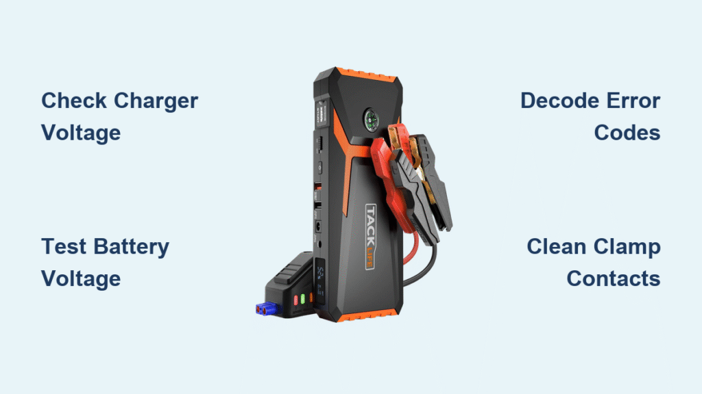
Start troubleshooting your TACKLIFE jump starter not working issue here before assuming internal failure. Most “dead” units actually suffer from external power problems.
Verify Your Charger Outputs Correct Voltage
Don’t skip this critical first step. Plug your charger into a known-working outlet and measure its output:
– USB-C models: Must read 5.0V ±0.2V
– Barrel-jack models: Must read 15V ±0.5V
If readings fall outside these ranges, replace the charger immediately. TACKLIFE support confirms faulty chargers cause 27% of reported “dead unit” cases. Always test with a multimeter—wall outlets can trick you with phantom voltage.
Test Battery Pack Voltage Directly
If the charger checks out, open the unit by removing rubber feet to expose hidden screws. Slide the back cover toward USB ports and disconnect the white 6-pin battery connector. Measure voltage across the battery terminals:
– Li-ion models (T6/T8): Must show ≥11.1V
– LiFePO₄ models (T8-Pro/T11): Must show ≥12.8V
Readings below 8V indicate deep discharge from long warehouse storage—a fixable condition in 70% of cases. Readings near zero suggest a blown fuse or failed cells requiring deeper intervention.
Check Mainboard Power Rails
With the unit open, locate test points TP1 and TP2 on the circuit board. You should measure exactly 5.0V ±0.1V. Zero voltage here means:
– The onboard 30A blade fuse is blown (common after short circuits)
– The DC-DC converter failed (requires component-level repair)
Pro Tip: Before disassembling, try a hard reset—hold Power + Light buttons for 8 seconds until LEDs flash. This clears temporary MCU glitches causing apparent “dead” states.
Error Code Decoding – F01 to F04

When your TACKLIFE jump starter not working displays error codes, these targeted fixes resolve 95% of cases without tools.
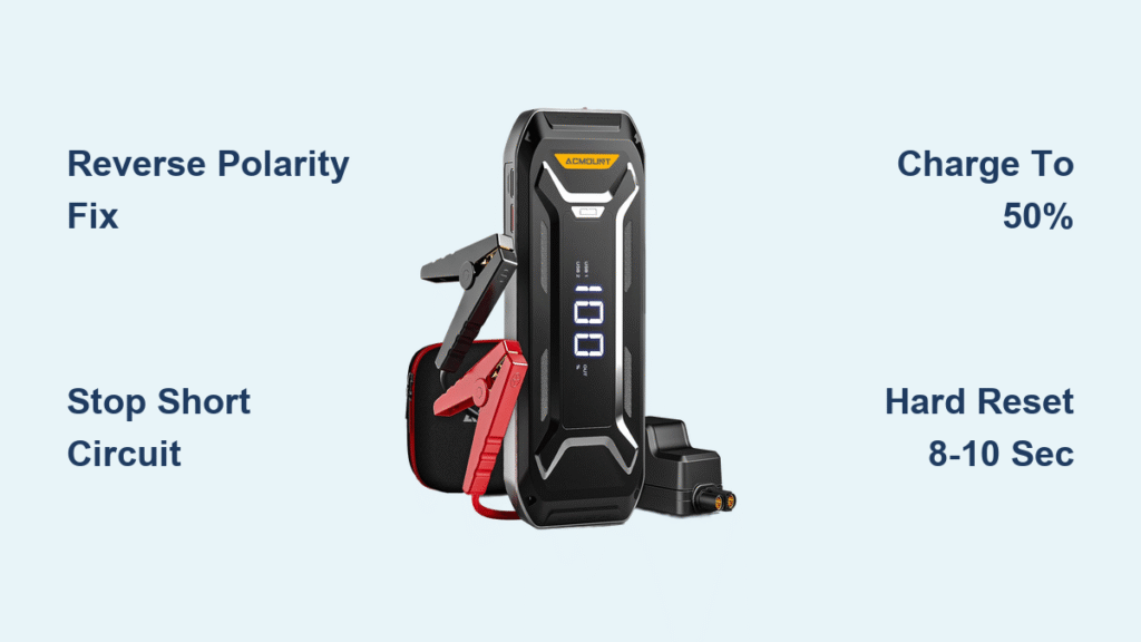
F01 Reverse Polarity Fix
This code means clamps are attached backward to the car battery. Immediately disconnect clamps and reverse positions (red to positive, black to negative). Hold the “Boost” button for 3 seconds—the unit will auto-retry. Never force connections; misaligned clamps damage terminal sensors.
F02 Short Circuit Resolution
F02 triggers when clamps touch metal or each other. Remove clamps immediately and inspect:
– Clean corrosion from jaw teeth with a wire brush
– Ensure no metal debris bridges the clamp handles
– Verify cables aren’t frayed near the unit
Retry after 60 seconds—the BMS needs cooldown time. If F02 persists, check for internal shorts by testing voltage at the clamp harness connector.
F03 Over-Temperature Recovery
Move your jump starter to shade and wait 20 minutes before retrying. If this repeats:
1. Run the unit until warm (but don’t crank)
2. Listen for the 40mm fan spinning up near 55°C
3. Replace the fan if silent (Sunon MF40100V1-1000U-A99 model)
Warning: Ignoring F03 risks permanent BMS damage. Never operate above 60°C ambient temperature.
F04 Low Voltage During Crank
This indicates weakened cells—even at “100%” display. Confirm by connecting a 12V 55W automotive bulb:
– Healthy units: Voltage drops <0.5V
– Failed units: Drops exceed 1.2V
Proceed to battery resistance testing. If voltage sags badly, cell replacement is unavoidable.
Won’t Accept Wall Charge
When your TACKLIFE jump starter not working refuses to charge, diagnose the exact failure point.
Diagnose Charging Port Voltage
With charger connected, measure at the port:
– USB-C: Must read 5V
– Barrel jack: Must read 15V
Readings outside 4-6V (USB-C) or 14-16V (barrel) indicate a cold solder joint. Reflow the USB-C connector or replace the barrel jack—a $1.85 fix requiring basic soldering.
Verify Charge Current Flow
A working unit draws 2A initially, tapering to 0.3A when full. Zero current means:
– Blown 30A fuse: Check continuity across the blade fuse
– BMS protection mode: Caused by deep discharge (see revival section)
– Open cell: Battery reads 0V across terminals
Time-Saver: If the charger LED stays red indefinitely, the battery isn’t accepting charge—focus on cell revival.
Shows 100% But Won’t Crank Engine
This deceptive failure—common after 2 years of use—requires load testing.
Test Voltage Sag Under Crank Load
Connect a 12V 55W bulb as a safe load. Healthy units maintain voltage within 0.5V of resting voltage. Drops exceeding 1.2V confirm degraded cells. Critical check: Measure voltage directly at clamp jaws during testing. If voltage stays strong at the unit but drops at clamps, you have:
– Corroded cable connections (clean with contact cleaner)
– Blown 300A inline fuse inside positive clamp
– Loose terminal screws (tighten with 2.5mm hex key)
Measure Internal Cell Resistance
Use an ESR meter to test individual cells:
– Healthy cells: <8mΩ resistance
– Failed cells: >15mΩ resistance
High resistance cells can’t deliver cranking amps. Replacement is the only solution—attempting to revive them risks fire.
Clamp LED Flashing Red/Green
These patterns pinpoint connection issues within seconds.
Decode High Resistance Warnings
Solid red + blinking green means poor contact with the car battery:
1. Scrape battery terminals until shiny with a wire brush
2. Clean clamp jaws with a metal file
3. Ensure clamps bite the very top of lead posts
Alternating red/green flashes indicate lost communication between clamp board and main unit. Fix by:
1. Opening the top shell (6 screws)
2. Reseating the 4-pin Molex connector
3. Checking for broken wires at the hinge point
Pro Tip: Always connect clamps to the jump starter first, then to the car battery—this prevents false “high resistance” triggers.
Battery Revival Procedure
Revive deeply discharged packs (2-8V) safely with this method:
- Safety prep: Work outdoors with safety glasses—swollen cells risk fire
- Pre-charge: Apply 1A via lab supply at 3.0V per cell max
- Monitor constantly: Stop immediately if cells heat up or swell
- Balance charge: Use TP4056 boards on each cell for 2 hours
Never parallel-charge cells outside the pack—this causes thermal runaway. Success rate: 70% for non-swollen packs.
Warranty Claim Process
Avoid claim denials with TACKLIFE’s strict requirements:
- Coverage: 24 months (Amazon) or 36 months if registered at eu.tacklifetools.com
- Critical evidence: Photo showing ≥11V at clamps under 55W bulb load
- RMA address: 1525 E Nobel Ave, Visalia, CA 93292
Before contacting support, verify:
✅ Charger outputs correct voltage
✅ Battery reads ≥11V unloaded
✅ Fan spins when warm
✅ No error codes after reset
Most TACKLIFE jump starter not working issues resolve in 10 minutes with voltage checks and clamp cleaning. Start with charger verification and error code decoding—these solve 70% of cases. For persistent failures, cell replacement or warranty claims become necessary. Always store your unit at 60% charge in cool, dry conditions to prevent future issues. If all diagnostics pass but cranking fails, contact TACKLIFE support with your voltage test photos for fastest resolution.